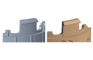
Figure 1: From 3D CAD model (left) to FEA meshed model [Image courtesy of Flex]
Finite element analysis can help design a robust mechanical architecture to pass one of the toughest tests in medical device design.
Giorgio Sardo, Flex
Time to market is a key factor for new medical product success. Designers now use modeling and simulation to pass one of the most severe tests: 60601-1, an international standard applicable to all medical electrical equipment and systems. By skipping costly trial-and-error iterations, they can quickly define the parameters for a robust mechanical architecture. Drop simulation can predict the test result and also support a failure analysis investigation.
If you’ve ever dropped your phone, your immediate concern is if it still works. Medical device users don’t experience the same anxiety if they drop their device because medical electrical equipment must meet a set of resistance requirements that ensures the device will work, even after an accidental drop.
Devices ranging from small glucose meters to huge computed tomography scanners must be compliant with the IEC 60601-1 standard, which ensures the equipment is designed to maintain basic safety and essential performance.
In the regulatory world this can be a complex issue requiring experts to agree on precise definitions. For example, we could say basic safety is ensured if the device does not provide an unacceptable risk when used normally or when one single element has failed; the essential performance can be considered as the function that, if lost, would produce an unacceptable risk.
From a mechanical standpoint, a device must have strength to avoid any loss of basic safety or essential performance produced by rough handling or excessive force from an impact or drop. Body-worn, hand-held and portable devices are tested for drop resistance based on the mean of three freefalls from at least 1m height on a 50mm wooden plate lying on a concrete or similar rigid base.
Two paths to passing the drop test
This is a tough test with two paths to passing:
- Trial and error: This can be a lengthy and expensive option that requires production of test samples, evaluation of each test performance, failure analysis, and the redesign of another iteration for testing until the requirements are met.
- The alternative is finite element analysis (FEA). A device is discretized in several small pieces and then deformation, stress and acceleration of the product components are checked after the simulated ground impact.
Before proceeding, let’s clarify what we mean by pieces that are used to mesh the model. They are elements into which the device’s 3D model can be divided (see Figure 1); they can be one-, two-, or three-dimensional, can include tetrahedrons and hexahedrons and can be connected one to the other by nodes that are respectively on each of the four or eight vertexes. This meshing can be done automatically by the software, but also refined and modified by the user depending on the FEA purpose.
There is more than one software program that can perform this analysis. We will consider ANSYS Explicit STR, which exploits the advantages of an explicit solver and makes the management of non-linearities that are contact points between different parts easier.
ANSYS also provides an implicit module that is normally used for static analysis or when the duration of the simulated event is relatively long (seconds or more). In this case, quadratic elements can be used as they have intermediate and vertex nodes and can provide a more accurate solution.
This module is used to calculate stresses and deformation from the interaction of two (or very few) parts, because handling nonlinear contacts with and without friction is comparatively complex using an implicit iterative numerical scheme.
The explicit module on the other hand is typically used for very short events (milliseconds) and can handle models with several parts and related contacts. This means that the whole device can be modeled and verified. The explicit approach follows a chronological path, thus performs a series of cycles where the timestep “I” solution depends and comes from the timestep “i-1” solution, thus no iterations and convergence checks are needed.
It is intrinsically unstable and very short timesteps are needed to make it stable. This is why it is so good for very short phenomenon and when you need to look at what’s happening in very short timesteps, like fractions of microseconds.
When it comes to meshing, ANSYS Explicit STR uses linear elements, not quadratic. Therefore, a mesh refinement is often needed in the area of interest. Tetrahedrons are generally preferred to hexahedrons for complex geometries like in plastic parts used in medical devices, and the meshing diagnostic tool provided by the software is used to verify the quality of the mesh before starting the simulation.
A primary step before and often after meshing is model simplification. Very complex features like screw threads or corner rounds will be removed whenever this does not affect the simulation results. It is important to remember that a finite element model is always a simplified version of reality and achieving the best balance between simplification and reliable results requires experience.
Now let’s examine the drop simulation. We can only evaluate a few milliseconds — depending on available computational power — therefore the meshed model is placed just a few hundredths of millimeters to the simulated ground floor. The speed of gravitational acceleration produced in 1m stroke is applied to the falling body as an initial condition. We then define the outputs to check, for example the strain and stress of components or features.
During the simulation the timestep is automatically adapted depending on the mesh elements’ deformation. To avoid a run crash, you can remove the bricks that are deforming too much, while checking the amount and location of these eroded elements. This is important because we don’t want to affect the physics of the problem and cheat. The alternative is to fix the problem back in meshing process — go back to pre-processing.
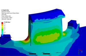
Figure 2: Von Mises stress (Mpa) [Image courtesy of Flex]
Data post-processing
The final step is data post-processing. The information can be extracted and plotted to understand if and where criticalities occur. For ductile materials the key indicator is the strain, while for more fragile ones stress — yield in particular — is the point of interest (see Figure 2). In some other cases the acceleration may be relevant.
At other times the acceleration may be relevant. In this case the drop simulation was to understand if a crystal soldered on the device PCB (Figure 3) was damaged due to the drop or because it was a weak sample.
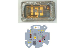
Figure 3: Broken crystal resonator (top) and crystal position on the PCB [Image courtesy of Flex]
Starting from the CAD model, all parts of the device were simplified and then meshed. The material properties were assigned to each part and the connections defined, then the electronic component was modeled as a plastic part and bonded to the PCB.
The simulation lasted 2ms and this was enough to see the first impact and the beginning of the bounce. An acceleration probe was placed on the component considered as a rigid body and the acceleration plotted (Figure 4)
This result was compared to the specification provided by the electronic component datasheet which specifies that the maximum allowable acceleration is 5000G for 3ms ½ sine wave. Looking at the data above, it could be concluded that the 5000 G for 3ms ½ sine wave was not reached. Moreover, looking at higher frequency results (10 kHz), a 11,000G peak can be identified as lasting for only a very short time (~ 0.05 ms) far below the limit identified by the supplier.
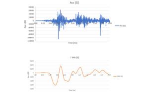
Figure 4: Average acceleration result on crystal rigid body (G vs ms), vertical direction.
The resulting top chart was very noisy and filtered using an ANSYS feature with a 2kHz filter producing the bottom chart. [Image courtesy of Flex]
We could conclude that the component breakage was due to the weakness of that specific sample and, once verified, avoid a long and expensive redesign. We can see clearly that even post-simulation, we can find cost and time savings and increase the efficiency of the design process.
This example clarified how the finite element analysis helps us understand the outcomes of a drop test. It demonstrates that several aspects can be considered, and how the creation and testing of multiple samples can be avoided.
The modeling phase is the key factor for reliable results. It requires experience and vision of the final target but takes considerably less time than building and testing multiple samples. This approach offers direct savings to the project timeline and budget, and a competitive advantage to the manufacturer who can get their product to market faster.

Giorgio Sardo is a design system senior staff engineer at Flex [Photo courtesy of Flex]
Giorgio Sardo, a design system senior staff engineer at Flex, has been working at the Flex Milan Design Center for more than 15 years. Sardo has broad experience in the design, prototyping and industrialization of various types of medical devices, such as autoinjectors, pen injectors, glucose meters, hand-held drug delivery devices and a dental tomograph.
The opinions expressed in this post are the author’s only and do not necessarily reflect those of MedicalDesignandOutsourcing.com or its employees.